(703) 659-8388
info@barriercables.net
Barrier Cable Systems, Inc.

Resources &
Specifications
Below you will find a couple Resources and Specifications that we use here at BCSI on a daily basis. The first is a resource that we created ourselves to provide a glimpse to our systems. The second are common specifications for barrier cable systems. You can download them and use them for your own projects.
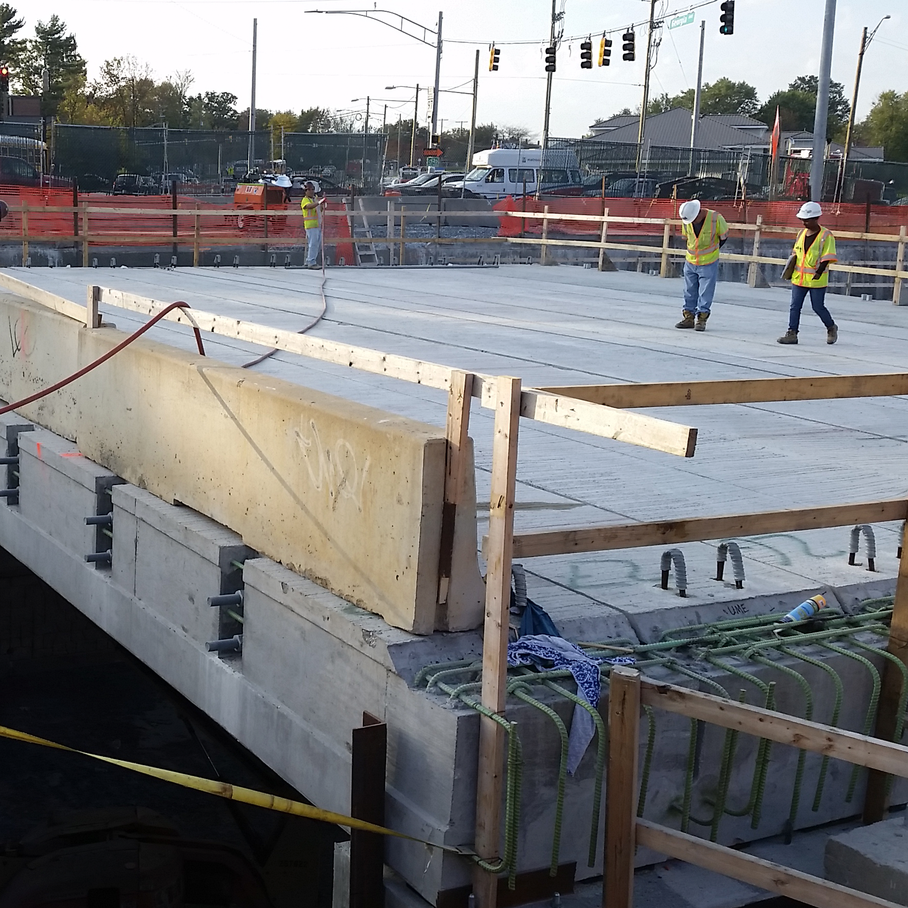
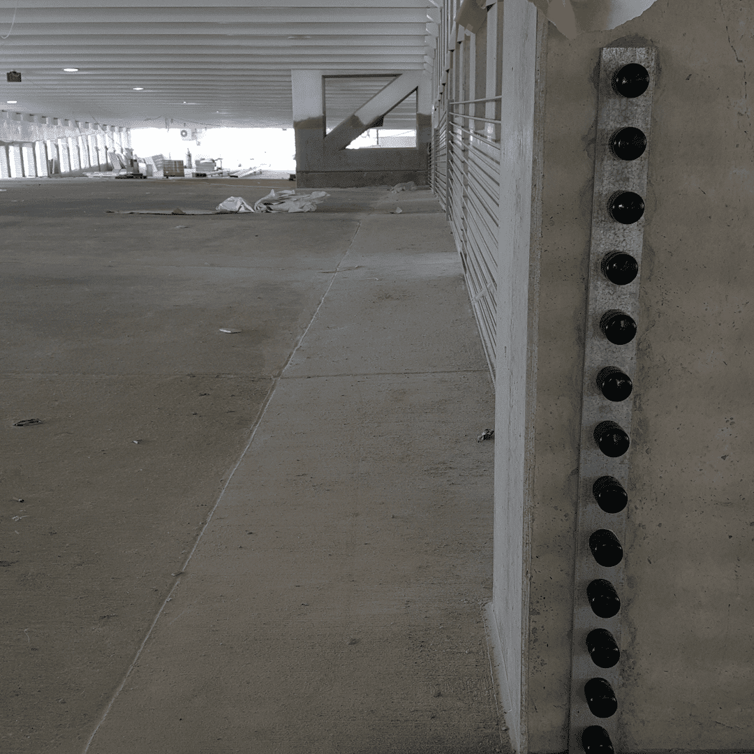
Barrier Cable
System
Barrier what?
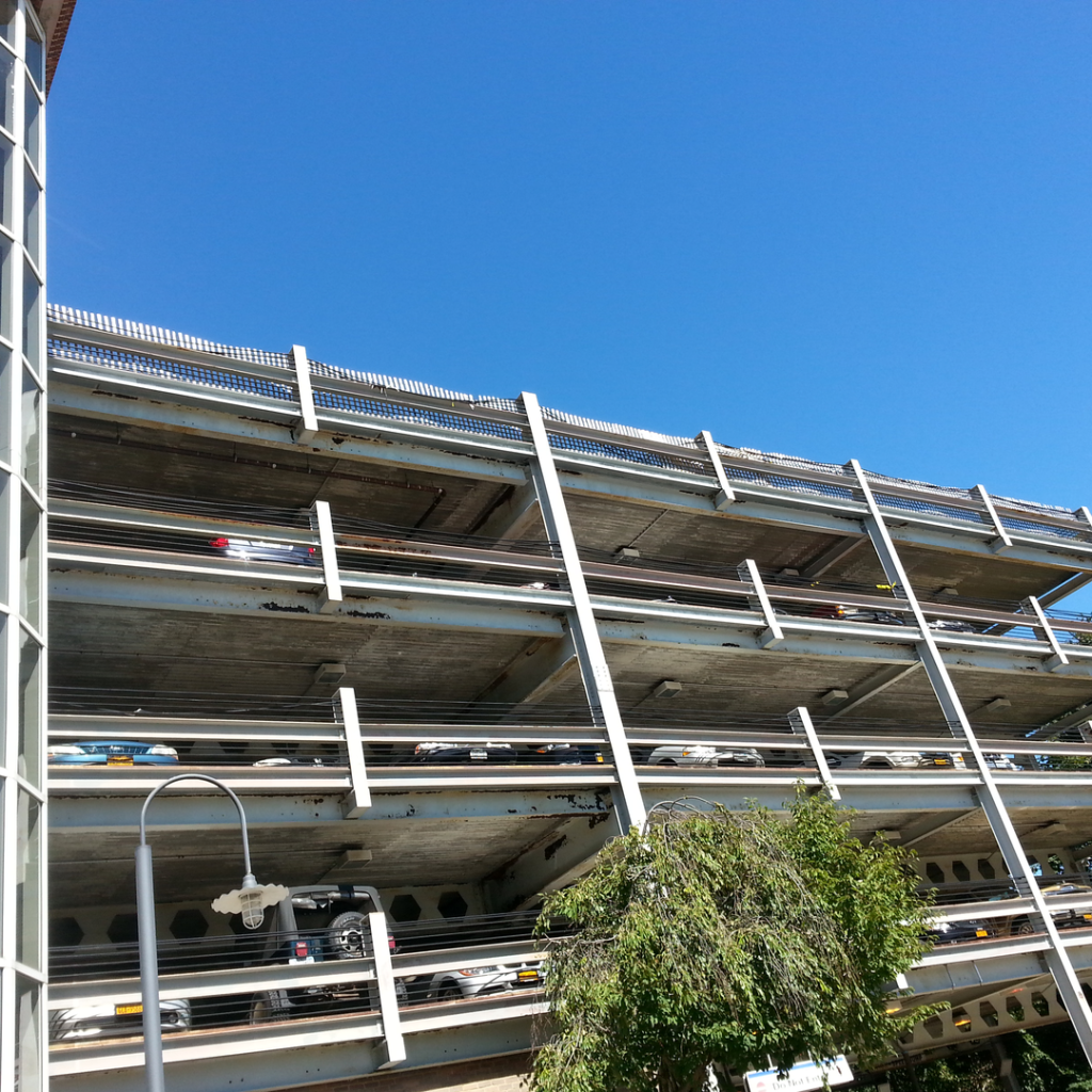
Barrier Cable Systems are a Specialty type of cable
guardrails that uses technologies derived from the
Post-Tensioning technique in order to achieve a
cable railing system capable of stopping vehicles in
compliance with the building codes with the highest
strength/weight and strength/cost ratios. wall…..
The use of very special carbon steel alloys (8 times
stronger than the regular steel that would be used
in common tube and plate guardrails…..) combined
with the Pre-tensioning of the cables allows the
barrier to resist to extremely high loads such as the
ones generated by a vehicle impact and do so in a
progressive way to arrest the vehicle “gently” when
compared to crashing into a concrete barrier
wall…..
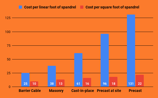
Why Cables?
Barrier Cable Systems are:
✓The most cost effective solution with an average direct cost of $30/lf.
✓The lightest solution, only 6 lbs/ft compared to 240 lb/ft for a 6” concrete crash
wall….. That translates in cost savings on the structure and its foundations.
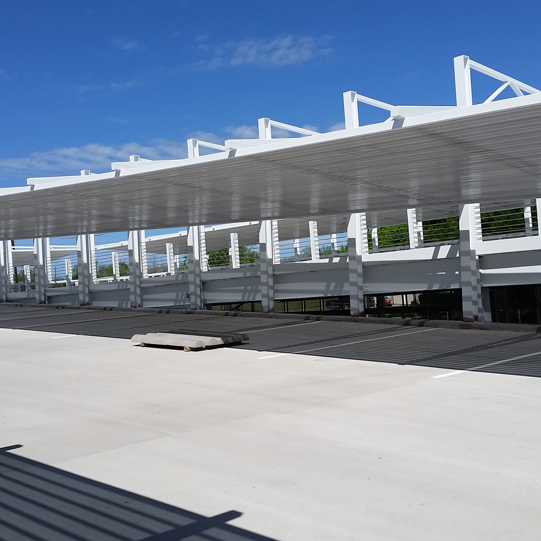
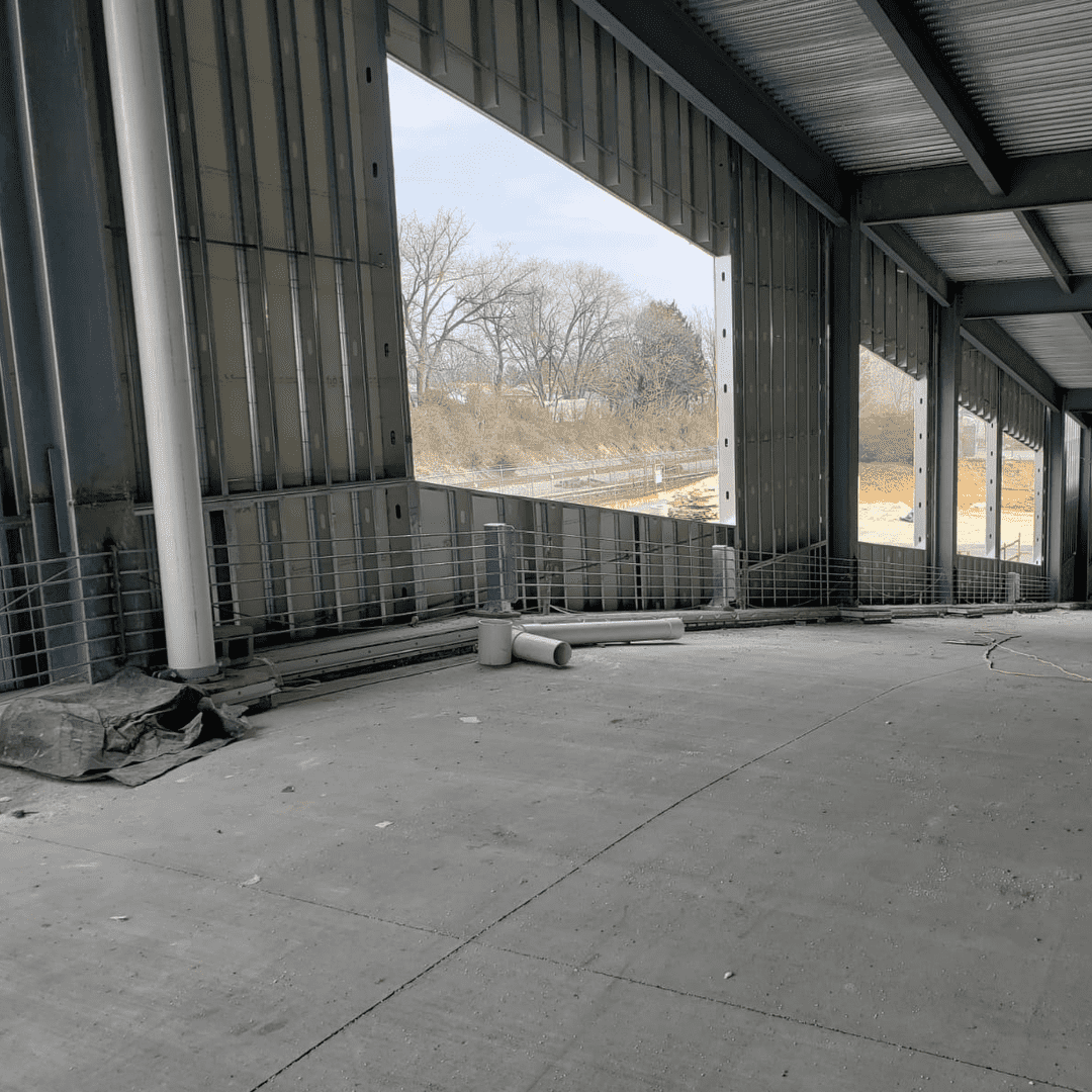
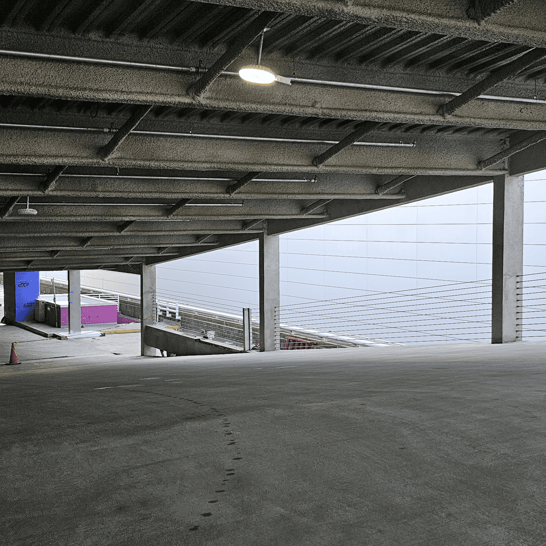
✓Create an open structure where mechanical ventilation systems may not be necessary
with direct and lifetime cost savings.
✓Façade cables create open structures where the need for sprinkler systems can be
waived (depending on local fire codes and authorities).
✓A cable barrier restraint system is the greenest solution with the smallest carbon
footprint of any vehicular barrier with the least and most effective use of materials
mostly recycled (post-consumer).
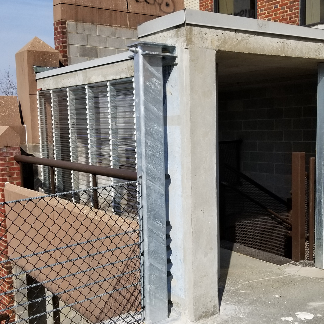
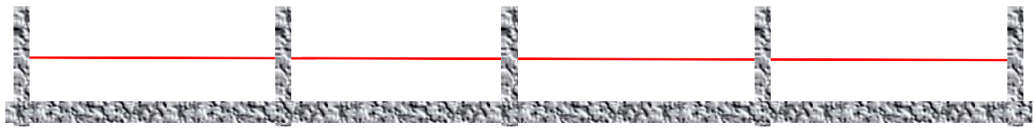
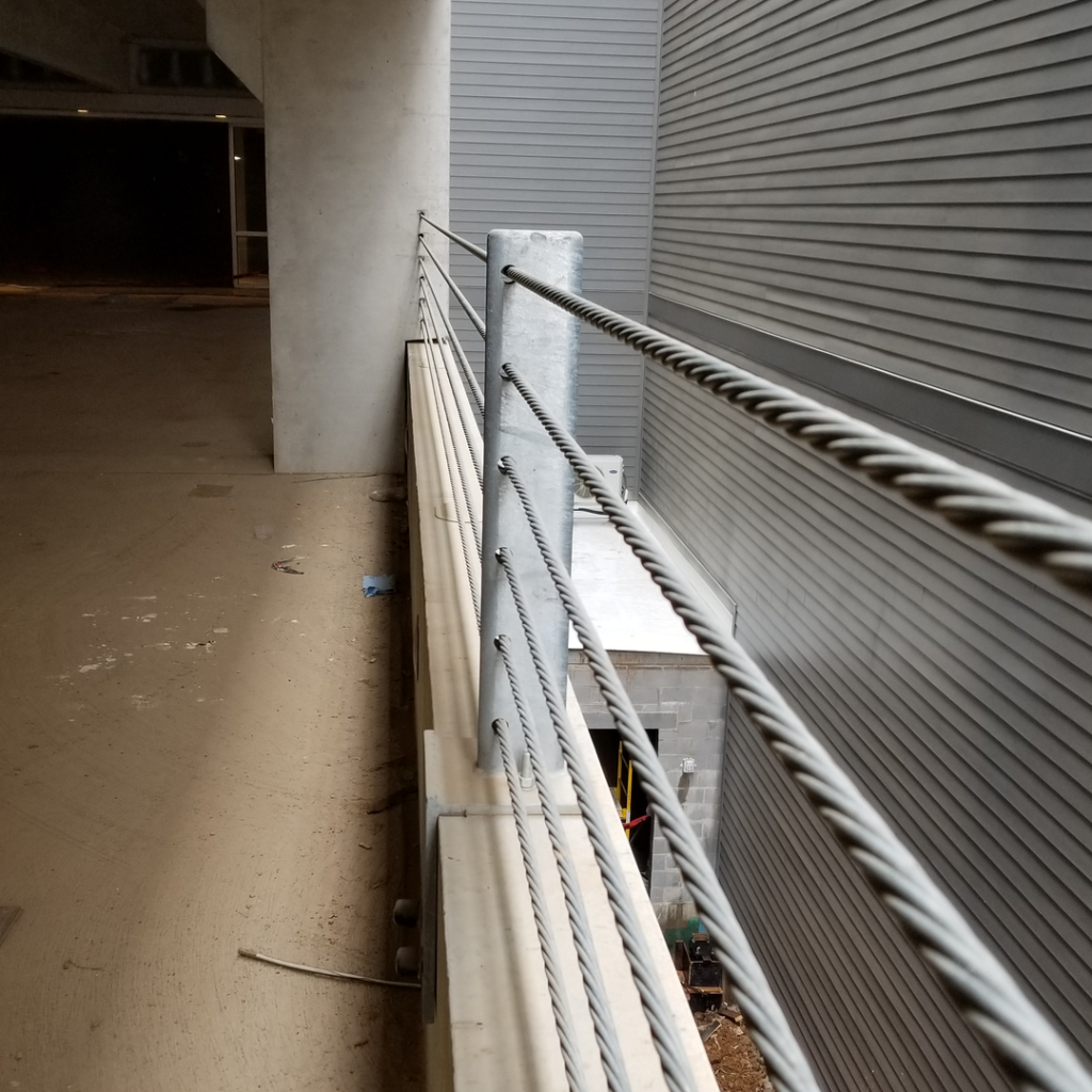
✓Very high strength galvanized steel cables are
tensioned to a force between 2,000 to 7,000 lbs
each between the columns of the structure.
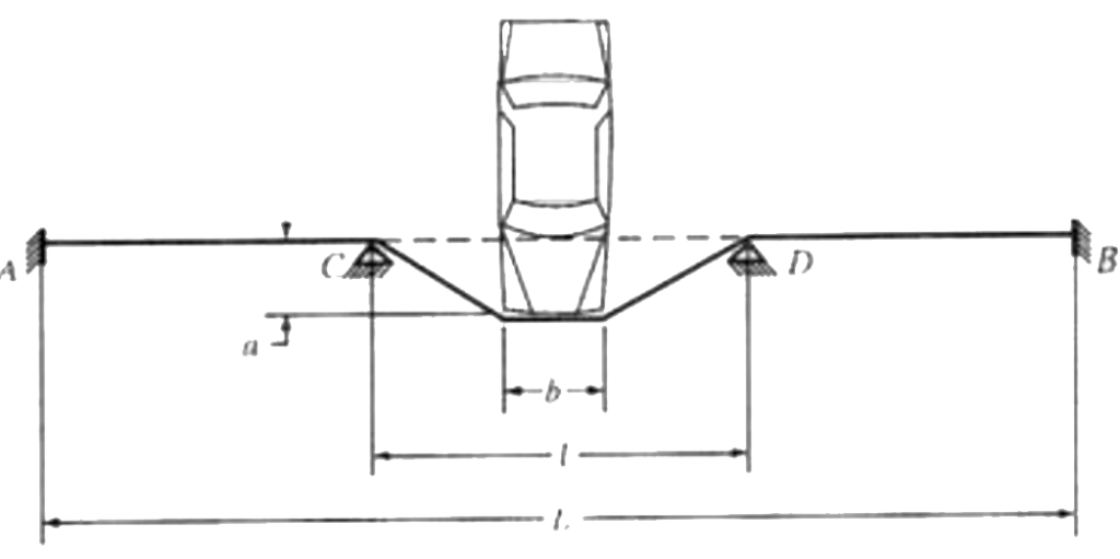
✓When impacted by a stray vehicle, the cables
stretch and react against the vehicle until
absorbing all its kinetic energy.
✓ For a barrier to be considered a vehicular
restraint, codes require that it resist to an
equivalent static load of 6,000 lbs with the
vehicle stopped within 18” of the cable plane.
✓This typically requires 3 cables…. Common 11
cable barriers result from the consideration of
pedestrian fall protection rules.
Barrier Cable Design Process
✓BC’s are life safety systems, the supplier/installer of the Barrier cable should provide
PE stamped fabrication/installation drawings and calculations demonstrating
compliance with the code requirements as applied to each specific structure and
eventually specific requirements defined by the Architect or Engineer of Record.
✓When steel posts or angles are required for the barrier, these shall be Engineered by
the barrier designer so that they are able to resist to the barrier loads (permanent and
impact) as well as direct impact when possible.
✓The EOR shall verify that the barrier cable reaction at the ends applied to the
structures columns or walls is compatible with their streng


Design Criteria
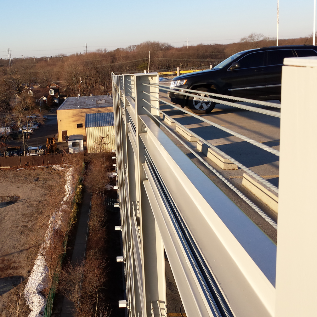
Vehicle Restraint
1 – Needed when ever a vehicle is exposed to a 12” or more possible drop. Minimum
height for vehicle restraint barriers is 33” (implies a minimum of 6 cables).
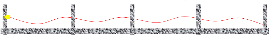
2 – Cable Sag Limitation : This criteria provides a minimum tension required to keep cables
from sagging excessively (more than ¼”) and maintain the barriers intended geometry.
3 – Deflection Criteria : Resist to a vehicle impact simulated by a 6,000 lbs static force
applied on a 12”x12” impact area located between 18” and 27” above the rolling surface
with no more than 18” deflection (beyond the edge) or any permanent deformation or
damage.
4 – All components and their anchoring to the Structure needs to be designed to resist
loads resulting from permanent tensions and impact reactions. EOR to verify that the
structure is capable of handling such loads.
Pedestrian Safety
1 – Needed whenever there is a possible drop/fall of 30” or more.
2 – Top rail located at a minimum 42” off the surface. Prevent the passage of a 4” sphere
anywhere from the deck to 34” above it and of an 8” sphere above that height.
3 – Be able to resist a single localized force of 200 Lbs at any point of the barrier and/or 50
lbs/ft on the top rail.
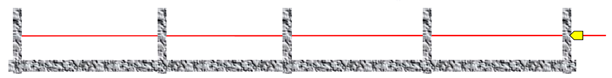
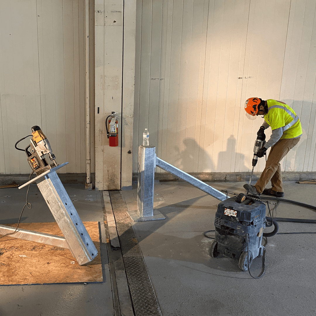
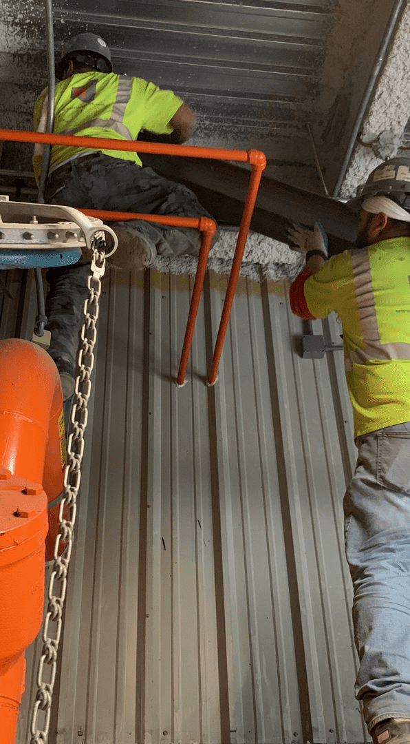
Field Installation step 1
Feed cable from the stressing side to the opposite end and perform the back seating to a minimum 28 Kips at the Dead End.
Field Installation step 2
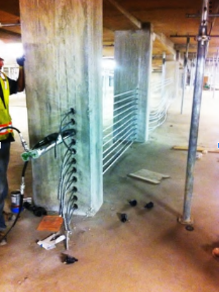
Tension cable with a calibrated PT Jack to there quired force, extend the piston an additional 3/8” to anticipate wedge set then release (elongation recording is not useful or required)
Field Installation step 3
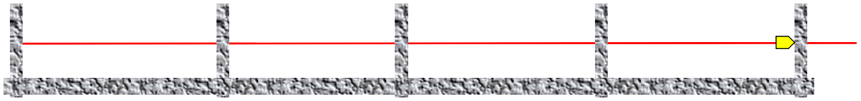
Perform the back seating to a minimum 28 Kips at the Live End (the 3/8” extra elongation are then lost as the wedge draws into a permanent lock)
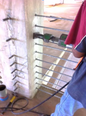
Field Installation step 4

Trim tails inside the anchor pockets, patch pockets with non-shrink dry pack grout, touch-up jack gripper bites with cold galvanizing compound.

PART 1- GENERAL
1.1 DESIGN
The 2009 IBC compliant barrier systems must meet the following requirements:
A. For automobile restraint: the systems must be capable of withstanding a single live load of 9,600 lbs. applied horizontally in any direction and location (including columns and steel posts) to the barrier systems, with the load center acting at 27” inches above the driving floor or ramp surface over a 12” square (3-cables max) without exceeding the allowable barrier deflection of 18-inches. The minimum height of the vehicular barrier is 2’9”.
B. For an only pedestrian restraint guard, the system must be capable of withstanding a single live load of 200 lbs. applied in any direction or any location and 50 lbs./LF for its top the top rail. Intermediate cables shall be able to resist to a 50 lbs. of force applied in any direction. Deflection shall be such that the top rail minimum elevation of 42” and cable spacing (4” maximum up to 34” of the floor than 8” maximum from there to 42” wherever a 30” or greater fall risk may occur) shall be guaranteed at all times.
The Design approach taken should be consistent with the requirement of each individual project. The barrier cable systems design must be capable of meeting both the automobile and pedestrian protection requirement of the code and must also limit defections between restraining members. The distance between anchorages and the initial tension applied to the system must be designed so that the total deflection of the system under impact load will not result in the damage to other building materials, adjacent property, or the public.
The system, all the system’s fabricated steel components and anchoring to the structural members shall be Designed and Installed by a Single Specialty Company whose qualifications are acceptable to the Engineer.


1.2 DEFINITIONS
A. Adjustable Anchorage: Adjustable devices that are used to connect the strand to the column.
B. Anchor: Normally a ductile iron casting which houses the wedges and is used to transfer the prestressing force to the concrete or bearing member.
C. Anchorages: A mechanical device comprising all components required to anchor the prestressing steel and permanently transmit the prestressing force to the concrete or bearing member.
D. Barrel Anchor: A Cylinder metal device housing the wedges and normally used with a bearing plate to transfer the prestressing force to the concrete or bearing member.
E. Back-stressing: A Stressing procedure that ensures that the wedges are properly seated into the anchor conical cavity.
F. Bearing Plate: manufactured carbon steel flat bar stock placed between the cast or machined barrel anchor and the column. G. Casting: See Anchor.
H. Coating: Material used to protect against corrosion
I. Donut: See Barrel Anchor
J. HDPE: Acronym for High-Density Polyethylene Plastic. Minimum density is 0.941gm/cm3
K. Inserts: Internally threaded devices designed to connect certain wedges type anchorages to the column.
L. Jack: A Mechanical device (hydraulic) used for applying stressing force to the barrier cable.
M. Jack Grippers: Wedges used in the jack to hold the strand during the stressing operation.
N. Jacking Force: The Maximum temporary force exerted by the jack while introducing the prestressing force into the concrete or bearing member through the barrier cable.
O. Kip: 1 Kip = 1000 lb. force (1Kip=4.44KN)
P. LDPE: Acronym for low-density Polyethylene Plastic. Minimum density is 0.91-gm/cm3
Q. MUTS: Acronym for Minimum Ultimate Tensile Strength. It is the force required to break the strand outside of the Anchorage area.
R. Nose piece: the front part of the jacking devices that fits into the stressing pocket, to align the jack with the anchor.
S. Pocket former: A Temporary device used at the stressing end during casting of the concrete to provide an opening in the concrete, allowing the stressing equipment access to the anchor cavity.
T. Seating Loss: the relative movement of the wedges into the anchor cavity during the transfer of the prestressing force to the anchorage, resulting in some loss of pre-stressing force. U. 7-wire strand: Six high strength steel wires twisted around a center (King) wire.
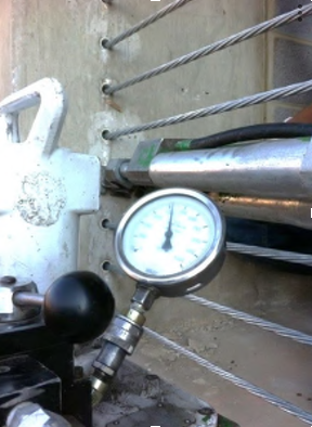
V. Stressing Equipment: Consists of a properly calibrated jack and pressure gauge with pump and hose.
W. Stressing Force: See Jacking Force
X. Wedges: Pieces of tapered metal with teeth which bite the stand during transfer of the jacking force the teeth are beveled at the front end to assure gradual development of the force over the length of the wedge. Two or three-piece wedges are normally used. Y. Wedge Set: See seating Loss.


1.3 SUBMITTALS
A. Shop Drawings: Installation drawings including plans, elevation, section, details, and noted prepared by or under the supervision of qualified installer detailing barrier cable layout and installation procedures including the following:
1. Numbers arrangement length, anchor location, anchor details, and designation of barrier cables. Installation and fabrication details of all angles, posts or fabricated steel members needed and their anchoring into the structure.
2. Stressing Procedures and jacking forces to result in the final effective forces.
3. Stressing records: Filled out by a testing agency during stressing operations:
• Name of the project
• Date of approved installation drawings used for installation and stressing
• Floor number and concrete placement area.
• Date of stressing operation.
• Weather conditions including temperature and rainfall
• Name and signature of the inspector
• Name of the individual in charge of stressing operation
• Serial or identification numbers of jacks and gage
• Date of jack and gage calibration certifications
• Gage pressure to achieve required stressing force per supplied calibration chart.
• Tendon identification mark.
• Actual gage pressure
B. Calculation note: Calculation note stamped by an experienced Professional Engineer and produced in accordance with the IBC and PTI (Post-Tensioning Institute) and providing at a minimum the following:
• Calculation of tendons minimum force for anti-sag criteria.
• Calculation of tendons maximum force under impact and verification of acceptance criteria for each cable run.
• Verification of the maximum deflection criteria for the barrier under impact for each significant cable.
• Determination of the pre-tensioning requirements to cover all criteria above including losses unless a specific procedure is in place to compensate for seating losses.
• Provide a load summary of permanent/accidental forces applied by the barrier for verification of their acceptability by the project Engineer of Records.
• Design calculations for all steel posts, angles or hardware used in the construction of the barrier cable. Design should be based on impact forces including the direct impact on steel posts used in the barrier construction.
C. Certified Mill Test Reports: shall be furnished upon request for each coil. Real or pack of strand containing as minimum the following information:
1. Coil Number
2. Ultimate Tensile Strength
3. Nominal Diameter and steel Area of strand.
D. Hardware Data Sheets: shall be furnished upon request for each hardware component used in the cable anchoring system.
E. Operation and Maintenance Manual: The system installer shall provide a system maintenance and operations guide to the Owner providing at a minimum the following data:
• Recommended inspection periodicity and procedures.
• Maintenance and repair procedures for minor damage (coating repair…).
• Action plan in case of major damage impairing the system functionality.
PART-2 PRESTRESSING STEEL
2.1 GENERAL SPECIFICATION
A. Prestressing steel used for barrier cable shall be wire steel strand which consists of one center wire with six wires spirally wrapped around it. The 7 Wire steel strand shall confirm to Galvanized Prestressed Concrete strand (GPC) Zinc coating weigh shall be class A as designated in ASTM A475, table 4. For vehicular applications, strand nominal diameter will be at least ½” and MUTS of 250 Ksi or better.
B. Use of plastic or Epoxy coated strands is not permitted under any circumstance.
C. Strand packs reels or coils shall be identified at the source as to grade, coil number and type.
2.2 ACCEPTANCE CRITERIA
A. Strand used for barrier cable shall meet the minimum requirement of the appropriate ASTM specification as the project specification. No exception will be permitted.
B. The Galvanized coating used for the barrier cable shall be free of damage so that the uncoated steel is not exposed to the elements. Small surface blemishes or schares do not expose the steel strand shall not be cause for rejections. A cracked or brittle coating will be rejected.
C. Small areas of damage may be repaired using the manufactures recommended methods provide that such repairs and repair methods have been approved by the responsible engineer of record. Repair material and Methods shall be compatible with the coating material.
PART-3 ANCHORING DEVICES
3.1 ANCHORS
Castings shall be nonporous and free of sand, blow holes, voids, and other defects. Casting shapes may be rectangular square or Cylindrical with a tapered corrival hole designed to receive the matched tapered wedges. Both the Casting Machined barrel anchors are used in the same way and should be rated to meet the impact load requirement specified.
3.2 INSERTS
These devices may be installed during the column placement (ferrule loops) or may be installed after the column is in place. All insert shall meet the ultimate pull out and shear load requirement of the design and, as a minimum shall meet the impact load requirement. Only inserts rated or minimum 2 to 1 safety ratio for ultimate pull out or shear is used unless test reports demonstrate equivalent performance in the field.
3.3 WEDGES
Wedges are made from carbon steel bar and are hardened by heat treatment after the indentations are machined on the inside and are designed to penetrate and hold the barrier cable the wedges must be under sufficient force to have the teeth engaged into the barrier cable to ensure the proper working action of barrier cable systems. The procedures used to accomplish this task must never exceed the maximum lateral force allowed by the column. Wedges shall be zinc plated or galvanized for corrosion resistance.
3.4 ADJUSTABLE ANCHORS
This device is used to mechanically seat the wedges and stress the barrier cable. It can be used to mechanically re-adjusted the tension of the barrier cable after installation or allow repair of the barrier cable after installation. The cable installed in these devices shall be back stressed per section 5.4B either before after the installation of the anchor.
3.5 BEARING PLATES
The bearing plates are intended to distribute the force over a greater bearing area of concrete to withstand the required impact load. The steel plate used shall meet ASTM A36. Size thickness will be adjusted to meet the design requirement,
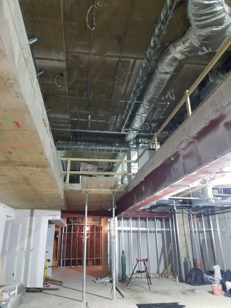
3.6 STRUCTURAL STEEL MEMBERS
Brackets or steel posts are sometimes used as an attachment to columns, in lieu of columns or to reduce the span between columns as well as for the purpose of mounting the cables or anchorage components. These elements should be custom designed for the project and will be able to stand permanent and impact forces including direct car impact when possible. Anchoring of such elements will be designed and detailed to ensure that their connection exceeds the required strength resulting from the impact on the barrier or directly on the element.
3.7 BARREL ANCHOR
Barrel anchors are cast or machined cylinder anchor devices (having a wedge cavity), these devices are designed to anchor the cable but do not have a bearing surface and shall be used with an appropriate bearing plate only.
3.8 ADJUSTABLE ANCHOR/INSERT TYPE
Wedges shall be initially mechanically and/or hydraulic seated at 80% MUTS into the barrel housing to ensure engagement of the wedges teeth into the barrier cable, the final force of the barrier cable is achieved mechanically through the threading adjustment of the stem of anchoring devices into the insert. The cable installed in these devices shall be back stressed in accordance with section 5.4B either before or after installation of the Anchor.
PART-4 COATING
4.1 COATING TYPE
All exposed Barrier cable elements shall be galvanized or zinc plated.
4.2 MINIMUM THICKNESS, DIAMETER, AND SPECIFIC PROPERTIES
Zinc coating shall be produced to comply with ASTM Specification A-475 Class A, table 4 Coating weight. Galvanized coatings shall be applied by either hot-dip, hot –dip and post drawing or electro planting process to ensure complete zinc around each individual wire of the strand.


PART5- INSTALLATION AND STRESSING
5.1 QUALIFICATIONS
Vehicular barrier cable system shall be installed in accordance with the following guidelines:
1. The system shall be Engineered holistically under the responsibility of a specialty Barrier Cable System specialty company manufacturing and certifying its installation in the field to comply with the approved plans and codes (2009 International Building Code).
2. The installation shall be performed under permanent direct supervision by PTI Certified installer or qualified technician; with three (3) years of experience of fifteen (15) projects of similar size and scope.
3. Proper calibrated stressing equipment shall be supplied for the application and/or barrier cable systems that are necessary to perform the work.
5.2 INSTALLATION OF BARRIER CABLE THROUGH COLUMN
A. At intermediate column, provide sleeves ensuring a hole which is a minimum 1/8” (3-mm) diameter larger than the barrier cable diameter used (including coating material). Spacing and position of the cables shall be executed by the concrete or precast supplier to match the dimensions given by the vehicular barrier cable shop drawings. Errors resulting from misunderstanding or lack of compliance with the barrier system drawings will be repaired by the concrete contractor (CIP or Precast) prior to the systems erection.
B. At end column, Anchors shall be recessed in the column prior to concrete placement or shall bear against the column surface (barrel anchor type). Position, spacing and reinforcing defined in shop drawings will be installed by the concrete (CIP or Precast) supplier per the systems shop drawings.
5.3 STRUCTURAL STEEL ANGLES & COLUMNS
A. Where applicable, structural steel support or anchoring angles shall be installed on the face of the column. These structural members shall be located far enough from the edge of the column so as not cause concrete spalling or cracking when the cables are stressed. The connections to the column shall develop the maximum impact design load for all the barrier cables at the location.
B. Where applicable, structural steel support or anchoring columns shall be installed as shown in the shop drawings. These structural members shall be positioned in the proper alignment so to avoid kinks in the barrier strands. Steel columns shall be anchored to the structure prior to the cable installation and shall not deflect under the barrier loads.
5.4 SPECIAL STRESSING CONSIDERATION
A. All the barrier cable shall be stressed to the stressing forces defined in the project approved shop drawings.
B. All fixed and stressing anchorages shall be back stressed. This back stressing is performed after the cables are stressed; the jack is then removed and placed so that the jack nose is bearing on the opposite side of the bearing member. The cable shall then be stressed to a force equal to 80% of the minimum ultimate tensile strength (MUTS) of the strand and no less than 25 Kips. In concrete applications, it is necessary to use a slotted plate to prevent damage to the backside of the member by the jack nose.
5.5 FINISHING OF ANCHOR RECESSES
A. Barrier cable tails shall be removed within 1 inch (25mm) from the face of the column using either an oxyacetylene torch or a metal cut off saw.
B. Anchor recessing (if possible) shall be filled with non –metallic non-shrink grout as soon as practicable after stressing and cutting, under no circumstances shall the grout used for this purpose contain chlorides or other chemicals known to be deleterious to the steel.
C. Prior to installing the grout the inside concrete surfaces of the recess shall be cleaned to remove laitance or grease to enhance the bond of the grout.
5.6 FINAL INSPECTION & PROTECTION OF BARRIER CABLE SYSTEMS
A. Barrier cable zinc coating damaged during installation, including back-stressing operations or tail cutting, shall be repaired with a cold galvanizing spray.
B. At anchorage columns, Barrier cable that passes through a hole in the column to anchorage shall have the hole sealed to prevent water from following the path of barrier cable to the anchorage unless the barrier cable slope prevents that from happening.
C. When cables tension is questioned, tension verification will be performed by means of an approved cable tension gage without removing or damaging the cables.
5.7 WARRANTY
At the completion of the project and prior to the final payment, the system supplier will provide a written warranty letter for a minimum period of three (3) years on all materials, components, and installation.